
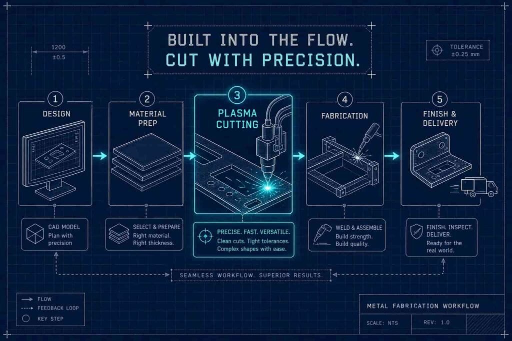
The quality of a finished weldment is often decided before a single weld bead gets laid. It’s decided at the cut. If the cut blanks come off the CNC plasma cutting table with accurate dimensions, square edges, and consistent geometry, the parts fit the fixture cleanly, the welder works faster, and the finished assembly meets print. If the cuts are sloppy, every step downstream pays for it. That’s why plasma cutting deserves more attention than it typically gets in conversations about fabrication quality.
This article covers how a plasma torch actually works, what it can and can’t cut reliably, how CNC plasma cutting connects to welding and assembly, and where plasma fits against other cutting processes. Whether you’re an OEM engineer evaluating a contract fabrication partner or a plant engineer sourcing replacement components, understanding the cut stage helps you ask the right questions before your job hits the shop floor. For a focused checklist on sourcing the right shop, see How to Choose a Contract Metal Fabricator for OEM Parts.
How a Plasma Torch Actually Cuts Through Metal
A plasma torch works by passing compressed gas through an electrical arc, which ionizes the gas and creates a superheated, electrically conductive jet. That jet, called plasma, reaches temperatures exceeding 20,000°C at the point of contact with the workpiece. At that temperature, metal doesn’t just heat up, it melts and is immediately expelled by the high-velocity gas stream, leaving the kerf behind.
Because the process depends on electrical conductivity, only conductive metals can be cut this way. Carbon steel, stainless steel, aluminum, copper, brass, and titanium are all fair game. Non-conductive materials — plastics, ceramics, wood, and non-conductive composites — cannot be processed by plasma. (Some composite materials with conductive fiber layers can be cut, but non-conductive composites are outside the process window entirely.) This isn’t a limitation most OEM fabricators run into often, but it’s worth knowing upfront when a job involves mixed materials.
Pilot Arc vs. Contact Start: Why It Matters for CNC Work
Modern plasma systems initiate the arc through a pilot arc, a small internal arc that establishes conductivity before the torch contacts the workpiece. This differs fundamentally from older contact-start systems, where the torch tip had to physically touch the metal to strike the arc. For CNC plasma cutting, pilot arc ignition is strongly recommended and is standard practice on production tables. It gives the control system a reliable, repeatable arc start on every cut pass without torch contact, which protects both the consumables and the accuracy of the first pierce on each part.
What the Nozzle Does to the Plasma Stream
The nozzle constricts the ionized gas into a narrow, high-velocity column. That constriction is what gives the plasma its cutting force. A smaller nozzle orifice produces a tighter, more focused stream and a narrower kerf; a larger orifice increases cutting capacity at the cost of some edge precision. Standoff distance, the gap between the nozzle and the workpiece, also affects cut quality directly. Too close and the torch risks arc instability and consumable damage; too far and the plasma stream loses focus. Both variables are managed differently in handheld plasma cutter use versus CNC table operation.
Materials and Thickness Ranges That Plasma Cutting Handles Reliably
Plasma cutting covers a wide range of conductive metals and material thicknesses, but the right system depends on what you’re cutting and how much of it. At the low end, handheld plasma cutter units running 50 to 80 amps cut reliably through 15 to 20mm of steel under typical operating conditions — useful for on-site maintenance and light processing, but not suited for high-volume CNC production runs. Industrial CNC systems in the 100 to 200 amp range handle 40 to 60mm, which covers the majority of structural fabrication work. High-power automated systems push past 150mm, territory that applies to shipbuilding and heavy energy equipment rather than most OEM component manufacturing. For a general overview of the process and its capabilities, see the plasma cutting reference.
Air plasma cutting, where shop air serves as the plasma gas, is common on lower-amperage systems and works well on carbon steel and aluminum plasma cutting applications. For stainless steel, or applications where edge oxidation must be minimized, nitrogen or argon-hydrogen mixtures are the better choice. Copper also deserves a specific note: it cuts fine with plasma, but requires roughly 20 percent more current for the same material thickness compared to carbon steel, which affects process planning when a job mixes copper components with structural steel parts on the same run.
Where CNC Plasma Cutting Adds Capability Over Handheld Units
The primary differentiator on CNC plasma cutting tables isn’t raw power, it’s torch height control (THC). THC systems monitor arc voltage in real time and automatically adjust the Z-axis to maintain a consistent standoff distance, even when the plate has bow or warp. On production runs with multiple parts nested across a full sheet, THC is what keeps cut quality consistent from the first part to the last. Without it, edge quality drifts as the torch encounters high spots and low spots across the plate, and that variation shows up in the weld fixture. For more on how THC works in practice, see this industry resource on torch height control for plasma cutting.
Where Plasma Loses Its Edge
Plasma is not the right process for every job. On sheet metal under approximately 6mm, the heat-affected zone becomes a real concern, edge quality drops, and laser cutting is the stronger choice. Laser produces a tighter kerf, a smaller HAZ, and cleaner edge geometry on thin material — advantages that matter when dimensional tolerance is tight. The plasma process also isn’t ideal for non-ferrous precision work where any heat distortion near the cut line creates problems downstream. Knowing where the process has limits is part of matching the right tool to the right part. For a modern comparison of laser and plasma capabilities, see laser cutting vs plasma cutting.
CNC Plasma Cutting and How It Enables Complex Part Geometries
A CNC plasma cutting table reads directly from a CAD file or DXF, which eliminates manual layout entirely. The programmer nests the required parts efficiently on plate stock, accounts for kerf offset, and the table executes the cuts. What comes off the table is a stack of shaped blanks: brackets, gussets, tank panels, frame rails, and flanges. For OEM customers who supply drawings or CAD files, the fabricator’s programming capability translates directly into part accuracy.
Efficient nesting matters more than it might seem. On a production run, material utilization directly affects cost per part. A shop that programs tight nests reduces scrap, and that efficiency gets passed back through the quote. It’s one of the less visible ways that a capable fabrication shop saves OEM customers money over the course of a contract.
Kerf Width and Fit-Up: The Connection Between Cut and Weld
On 10 to 25mm carbon steel, CNC plasma cutting produces a kerf width typically in the range of 2 to 4mm, depending on system type, amperage, and nozzle size. High-definition plasma systems run tighter, often 1.7 to 2.2mm across that thickness range. That kerf width has to be factored into part programming, or joint fit-up suffers. A part programmed without accounting for kerf will come out undersized, and the resulting gap in the weld joint affects both weld quality and finished dimensions. Always confirm offsets with test cuts when setting up a new material or amperage combination.
A plasma-cut edge that’s square, consistent, and clean goes into the weld fixture faster and requires less grinding or re-fitting. That time savings adds up across a production run. When the cut stage is managed well, the welding stage runs smoother and finished weldments come out closer to print. For guidance on downstream welding decisions and production options, our piece on Robotic vs Manual Welding for OEM Production Parts explains trade-offs relevant to OEM volume work.
How Plasma Cutting Compares to Laser, Oxy-Fuel, and Waterjet
OEM engineers evaluating fabrication partners often ask why a shop uses plasma rather than laser, or the reverse. The answer comes down to material thickness, edge quality requirements, and cost per cut, and no single process wins across all three.
Laser cutting wins on thin sheet metal, typically under 6mm, where edge quality and tight tolerances matter most. It produces a narrower kerf, a smaller heat-affected zone, and cleaner edge geometry, and it’s fast on thin material. The tradeoff is equipment cost: fiber laser systems generally run two to five times higher than comparable plasma setups, and that cost shows up in the quote. For a contract fabricator producing heavy-gauge structural components, tank panels, and frame weldments in the 6 to 38mm range, plasma hits the right balance of speed, capability, and cost.
When the Job Calls for Something Other Than Plasma
Oxy-fuel cutting is viable for very thick carbon steel where budget is tight and tolerances are loose. It’s slower than plasma and produces more heat, but the equipment cost is low and the process handles steel sections that push past what most plasma systems can manage. Waterjet is the right choice when heat input can’t be tolerated at all, or when the job includes non-conductive materials. It’s the slowest and most expensive option per linear foot, but the only thermal-free process that handles composites, stone, glass, and heat-sensitive metals without distortion. For a practical comparison of cutting processes, see this overview of plasma vs laser vs waterjet. A capable fabricator matches the cutting process to the part before the first torch fires; that decision is part of the engineering value a good shop brings to every quote.
Integrating Plasma Cutting Into a Full-Service Fabrication Workflow
The real value of CNC plasma cutting in OEM fabrication shows up not in the process itself, but in how the cut stage connects to everything that follows. When cutting, forming, and welding happen under one roof, there are no handoffs between vendors, no translation errors between what the cut shop produced and what the weld shop expected, and no compounding dimensional variation that locks a bad fit into the finished assembly.
At Engineered Welding, Inc., the workflow runs as a continuous sequence. A customer submits a CAD file or print, the shop programs and cuts the parts, runs them through the press brake if forming is required, and moves them directly to the weld fixture. The dimensions that came off the plasma table are the dimensions that go into the weldment. That continuity supports consistent, drawing-accurate parts at production volume, and it reduces the risk of compounding error that multi-vendor supply chains introduce at every handoff.
Why Separate Vendors Create Compounding Error
When an OEM sources cut blanks from one shop and welding from another, dimensional variation compounds at each handoff. A cut part that’s 1mm off in a critical dimension fits the weld fixture poorly. The welder compensates, or doesn’t, and that variation gets locked into the finished assembly. A single-source fabricator can catch and correct those issues before they become welding problems, because the same team that programmed the cuts is also responsible for the weldments that result.
Consumables, Maintenance, and Plasma Safety Essentials
A plasma cutting system runs as well as its consumables and the operator maintaining them. The electrode and nozzle wear fastest and affect cut quality most directly. The electrode contains a hafnium tip that erodes with each pierce; once the pit depth in that tip exceeds approximately 1.6mm, arc stability drops, bevel angle increases, and cut quality deteriorates. Replace the electrode and nozzle together, not individually. Running a fresh nozzle against a worn electrode, or vice versa, shortens the life of both and produces inconsistent kerf width between replacements.
Swirl rings and shield caps need periodic inspection but hold up longer under normal use. Replace the swirl ring approximately every fifth electrode change. Replace the shield cap when slag buildup can’t be cleaned off or when the ceramic shows visible damage. On high-production systems, tracking replacement intervals against pierce count, rather than calendar time, gives a far more accurate picture of actual wear.
Shop Safety Requirements for Plasma Cutting Operations
Plasma cutting produces intense arc light, UV radiation, fumes, and sparks. Minimum PPE includes a welding helmet with at least a shade #5 lens (higher shades may be appropriate at elevated amperages), flame-resistant clothing covering all exposed skin, dry insulated welding gloves, and leather boots. Respiratory protection is required when ventilation is limited, particularly when cutting galvanized steel, coated materials, or stainless steel, where fume composition is a real health concern.
Shop setup requires at least 25 to 35 feet of clearance between the cutting area and combustible materials, a non-conductive ground surface, functional fume extraction, and a fire extinguisher within reach. Power cables, hoses, and nozzle connections should be inspected regularly for wear or damage. In any professional fabrication environment, these measures aren’t a checklist, they’re baseline operating standards.
Frequently Asked Questions
What does plasma cutting do?
Plasma cutting uses a jet of ionized gas, heated past 20,000°C by an electrical arc, to melt through electrically conductive metal and blow the molten material out of the cut path. The result is a shaped blank with a kerf, the width of material removed along the cut line, ready for forming or welding.
Which is better, plasma or laser cutting?
Neither wins outright — it depends on the part. Laser cutting produces a tighter kerf and smaller heat-affected zone on thin sheet under about 6mm, so it’s the better choice when tolerance is tight and material is thin. Plasma cutting is faster and more cost-effective on heavier gauge material, roughly 6 to 38mm, which covers most structural OEM fabrication work.
What are the disadvantages of plasma cutting?
Plasma cutting has a wider heat-affected zone than laser or waterjet, which limits its precision on thin material and heat-sensitive non-ferrous parts. It also can’t cut non-conductive materials like plastics, ceramics, or standard composites, and consumables (electrodes and nozzles) wear with pierce count and need regular replacement to hold cut quality.
Is plasma cutting safe?
Yes, when standard PPE and shop safety practices are followed. That means a welding helmet with at least a shade #5 lens, flame-resistant clothing, insulated gloves, functional fume extraction, and adequate clearance from combustibles. Respiratory protection matters most when cutting galvanized or coated steel, where fume composition is a genuine health concern.
What can plasma not cut?
Plasma cutting can’t process non-conductive materials, including plastics, ceramics, wood, and most composites, because the process depends on electrical conductivity to sustain the arc. Some composites with conductive fiber layers are an exception, but non-conductive composites are outside the plasma process window entirely — waterjet is the right process for those materials instead.
Do you need a respirator for plasma cutting?
Respiratory protection is required whenever ventilation is limited, and it becomes especially important when cutting galvanized steel, coated materials, or stainless steel, since fume composition in those cases poses a real health risk. Well-ventilated shops with functional fume extraction reduce but don’t eliminate the need for respiratory protection during extended cutting runs.
Precision at the Cut Stage Pays Dividends Everywhere Downstream
CNC plasma cutting is an efficient, capable process for producing weld-ready blanks from conductive metal across a wide range of thicknesses. Its value in a fabrication workflow depends entirely on how well it connects to the steps that follow. Cut parts that come off the table dimensionally accurate, with consistent edge quality and proper kerf offset, go into the weld fixture faster and produce better weldments. That’s not a minor efficiency gain, it’s the foundation of repeatable, production-volume quality.
For OEM manufacturers who need consistent, drawing-accurate fabricated components at production volumes, the right answer is a fabricator who manages the full sequence from first cut to final weld, with the accountability to get it right at every operation. Engineered Welding, Inc. brings cutting, forming, and welding together under one roof so that nothing gets lost between steps. If you have a fabrication project ready to quote, submit your CAD files or prints and get a fast turnaround from a shop that builds parts right the first time. Learn more about market trends and our capabilities in Custom Metal Fabrication: Trends for OEMs in 2026, Engineered Welding, Inc.